Persónuverndaryfirlýsing: Persónuvernd þín er mjög mikilvæg fyrir okkur. Fyrirtækið okkar lofar ekki að birta persónulegar upplýsingar þínar til allra útgjalda með skýrum heimildum þínum.
Gerð nr.: NSO4GU3AB
Samgöngur: Ocean,Air,Express,Land
Greiðsla Tegund: L/C,T/T,D/A
Incoterm: FOB,EXW,CIF
4GB 1600MHz 240-PIN DDR3 UDIMM
Endurskoðunarsaga
|
Revision No. |
History |
Draft Date |
Remark |
|
1.0 |
Initial Release |
Apr. 2022 |
|
![]()
Panta upplýsingatöflu
|
Model |
Density |
Speed |
Organization |
Component Composition |
|
NS04GU3AB |
4GB |
1600MHz |
512Mx64bit |
DDR3 256Mx8 *16 |
Lýsing
Hengstar óbuffed DDR3 SDRAM DIMMS (óstífluðum tvöföldum gagnahraða samstilltur DRAM Dual In-Line Memory Modules) eru lítill kraftur, háhraða aðgerð minni einingar sem nota DDR3 SDRAM tæki. NS04GU3AB er 512m x 64-bita tvö röð 4GB DDR3-1600 CL11 1,5V SDRAM óbuffed DIMM vöru, byggð á sextán 256m x 8 bita FBGA íhlutum. SPD er forritað á JEDEC Standard DREDNY DDR3-1600 tímasetningu 11-11-11 við 1,5V. Hver 240-pinna DIMM notar gull snertingar fingur. SDRAM Unbuffered DIMM er ætlað til notkunar sem aðalminni þegar það er sett upp í kerfum eins og tölvum og vinnustöðvum.
Eiginleikar
KRAFTUR: VDD = 1,5V (1.425V til 1.575V)
VDDQ = 1,5V (1.425V til 1.575V)
800MHz FCK fyrir 1600MB/sek/pinna
8 Óháður innri banki
Forritanleg CAS leynd: 11, 10, 9, 8, 7, 6
Forritanlegt aukefni: 0, CL - 2, eða CL - 1 klukka
8-bita forstillingu
Burst lengd: 8 (samlagast án nokkurra marka, í röð með upphafsfangi „000“), 4 með TCCD = 4 sem leyfir ekki óaðfinnanlegt að lesa eða skrifa [annað hvort á flugu með því að nota A12 eða MRS]
Innri (sjálf) kvörðun; Innri sjálfs kvörðun í gegnum ZQ PIN (RZQ: 240 Ohm ± 1%)
Á lúkningu ODT með ODT pinna
A
SKILYRÐUN endurstillingar
Styrkjanleg drifstyrkur gagnaútgangs
Fljótandi við grannfræði
PCB: Hæð 1,18 ”(30mm)
Rohs samhæfir og halógenlaus
Lykil tímasetningar breytur
|
MT/s |
tRCD(ns) |
tRP(ns) |
tRC(ns) |
CL-tRCD-tRP |
|
DDR3-1600 |
13.125 |
13.125 |
48.125 |
2011/11/11 |
Heimilisfang töflu
|
Configuration |
Refresh count |
Row address |
Device bank address |
Device configuration |
Column Address |
Module rank address |
|
4GB |
8K |
32K A[14:0] |
8 BA[2:0] |
2Gb (256 Meg x 8) |
1K A[9:0] |
2 S#[1:0] |
Pinna lýsingar
|
Symbol |
Type |
Description |
|
Ax |
Input |
Address inputs: Provide the row address for ACTIVE commands, and the column |
|
BAx |
Input |
Bank address inputs: Define the device bank to which an ACTIVE, READ, WRITE, or |
|
CKx, |
Input |
Clock: Differential clock inputs. All control, command, and address input signals are |
|
CKEx |
Input |
Clock enable: Enables (registered HIGH) and disables (registered LOW) internal circuitry |
|
DMx |
Input |
Data mask (x8 devices only): DM is an input mask signal for write data. Input data is |
|
ODTx |
Input |
On-die termination: Enables (registered HIGH) and disables (registered LOW) |
|
Par_In |
Input |
Parity input: Parity bit for Ax, RAS#, CAS#, and WE#. |
|
RAS#, |
Input |
Command inputs: RAS#, CAS#, and WE# (along with S#) define the command being |
|
RESET# |
Input |
Reset: RESET# is an active LOW asychronous input that is connected to each DRAM and |
|
Sx# |
Input |
Chip select: Enables (registered LOW) and disables (registered HIGH) the command |
|
SAx |
Input |
Serial address inputs: Used to configure the temperature sensor/SPD EEPROM address |
|
SCL |
Input |
Serial |
|
CBx |
I/O |
Check bits: Used for system error detection and correction. |
|
DQx |
I/O |
Data input/output: Bidirectional data bus. |
|
DQSx, |
I/O |
Data strobe: Differential data strobes. Output with read data; edge-aligned with read data; |
|
SDA |
I/O |
Serial |
|
TDQSx, |
Output |
Redundant data strobe (x8 devices only): TDQS is enabled/disabled via the LOAD |
|
Err_Out# |
Output (open |
Parity error output: Parity error found on the command and address bus. |
|
EVENT# |
Output (open |
Temperature event: The EVENT# pin is asserted by the temperature sensor when critical |
|
VDD |
Supply |
Power supply: 1.35V (1.283–1.45V) backward-compatible to 1.5V (1.425–1.575V). The |
|
VDDSPD |
Supply |
Temperature sensor/SPD EEPROM power supply: 3.0–3.6V. |
|
VREFCA |
Supply |
Reference voltage: Control, command, and address VDD/2. |
|
VREFDQ |
Supply |
Reference voltage: DQ, DM VDD/2. |
|
VSS |
Supply |
Ground. |
|
VTT |
Supply |
Termination voltage: Used for control, command, and address VDD/2. |
|
NC |
– |
No connect: These pins are not connected on the module. |
|
NF |
– |
No function: These pins are connected within the module, but provide no functionality. |
Athugasemdir : PIN -lýsingartöflan hér að neðan er yfirgripsmikil listi yfir alla mögulega pinna fyrir allar DDR3 einingar. Allir pinnar sem taldir eru upp í maí Ekki vera studdur á þessari einingu. Sjá PIN -verkefni fyrir upplýsingar sem eru sérstaklega við þessa einingu.
Hagnýtur blokkarmynd
4GB, 512MX64 eining (2. ríki x8)


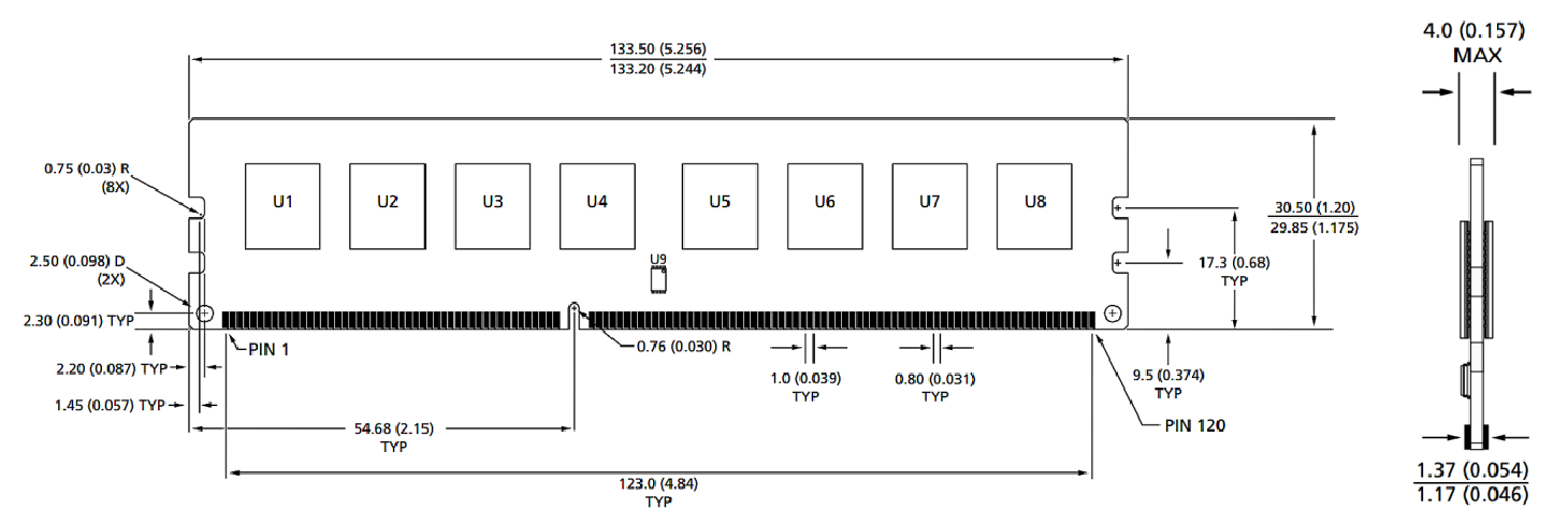
Málstærð
Framhlið

Framhlið

Athugasemdir:
1. Allar víddir eru í millimetrum (tommur); Max/mín. Eða dæmigert (type) þar sem tekið er fram.
2.þol á öllum víddum ± 0,15mm nema annað sé tekið fram.
3. Málsmyndin er eingöngu til viðmiðunar.
Vöruflokkar : Aukahlutir iðnaðar Smart Module


Persónuverndaryfirlýsing: Persónuvernd þín er mjög mikilvæg fyrir okkur. Fyrirtækið okkar lofar ekki að birta persónulegar upplýsingar þínar til allra útgjalda með skýrum heimildum þínum.

Fylltu út frekari upplýsingar svo það geti haft samband við þig hraðar
Persónuverndaryfirlýsing: Persónuvernd þín er mjög mikilvæg fyrir okkur. Fyrirtækið okkar lofar ekki að birta persónulegar upplýsingar þínar til allra útgjalda með skýrum heimildum þínum.